We use cookies to make your experience better. To comply with the new e-Privacy directive, we need to ask for your consent to set the cookies. Learn more.
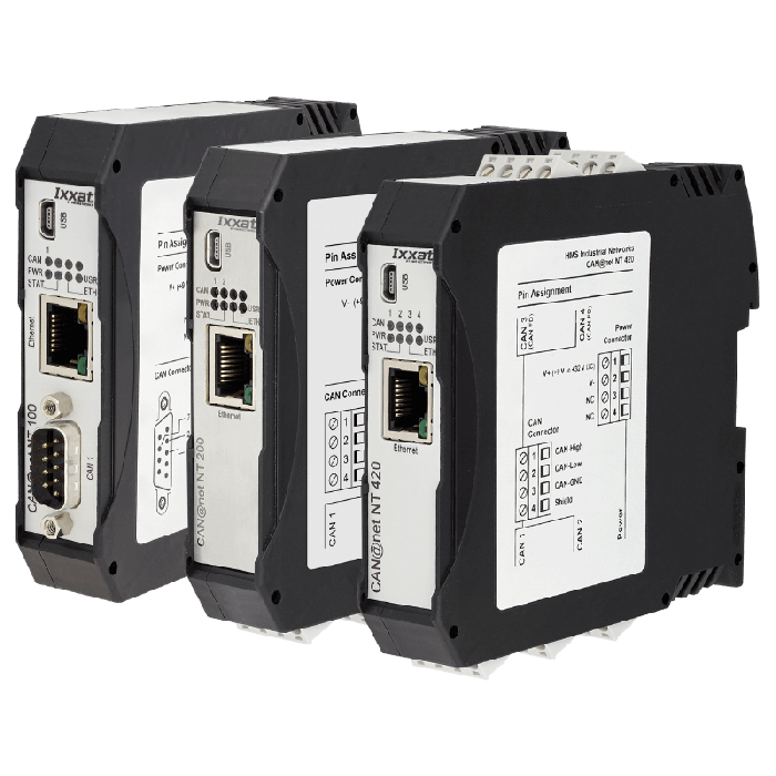
The CAN@net NT is offered in three variants, as CAN@net NT 100 with one classic CAN channel and D-Sub 9 connector, as CAN@net NT 200 with two classic CAN channels and as CAN@net NT 420 with four CAN channels, of which two channels can be switched between CAN and CAN FD. All devices offer three operation modes and can be used as a PC interface as bridge and gateway.
HOW IT WORKS
OPERATION MODES
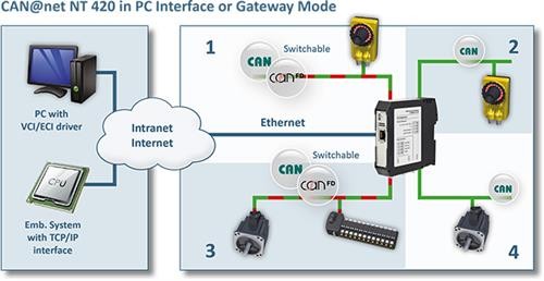
CAN-Ethernet Gateway
In gateway mode the CAN@net NT can be directly accessed from e.g. Windows, Linux, VxWorks or QNX based systems as well as from embedded systems, by using a simple ASCII protocol over a standard TCP/IP socket. As CAN-Ethernet Gateway, the CAN@net NT offers easy, flexible access to four independent CAN systems (two CAN FD) via a LAN or via the Internet.
PC Interface
With the included VCI driver for Windows, the CAN@net NT can be operated like all Ixxat CAN PC interfaces. With the CAN@net NT, all VCI-based Ixxat tools, such as the canAnalyser, as well as customer-specific applications based on the VCI driver can be used. The VCI CAN driver offers the possibility to communicate with up to 128 CAN@net NT devices at the same time.

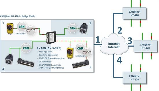
CAN-Ethernet-CAN Bridge
By using up to four CAN@net NT 420 (two CAN@net NT 100/200), a CAN-Ethernet-CAN bridge can be implemented, with each up to four independent CAN channels (2 for the CAN@net NT 200, 1 for the CAN@net NT 100) per device. The bridge allows the exchange of CAN messages between CAN systems over long distances via TCP/IP, using existing Ethernet infrastructures. The segmentation of CAN systems also increases the reliability and failure safety of the entire system.
FUNCTIONS
Filtering and multiplexing
With the help of mapping tables, the exchange of messages between all channels can be configured very flexibly. Filter and conversion rules can be applied to the CAN and CAN FD messages. As a result, the bus load in the individual networks can be reduced since only relevant messages are transmitted to the other network. For SAE J1939 applications a special mapping table is provided, adapted to the specific parameters. The data multiplexing/demultiplexing functionality enables the mapping of e.g. CAN-FD data to several standard CAN messages and vice versa.
Action Rules
In response to received messages, device or CAN bus status events, a variety of actions can be performed automatically, e.g. sending messages (CAN, CAN FD, MQTT), changing device settings or switching device LEDs. Action rules are created through intuitive drop-down menus for events and actions within the Windows-based device configuration tool or by using LUA scripts.
MQTT for cloud connection
Whether device status or CAN/CAN FD data, the MQTT functionality of the CAN@net NT enables transmission of various information to the cloud – easily programmable using action rule lists. With free available broker services and APPs, e.g. status messages or system values can be easily transmitted to your smartphone or other devices.
Cyclic transmission
The cyclic transmission feature enables cyclic forwarding of messages. Both, messages and cycle times are defined within a central cyclic transmission table.
CONFIGURATION
HOW-TO VIDEOS
View our how-to videos on youtube to learn more about the configuration...
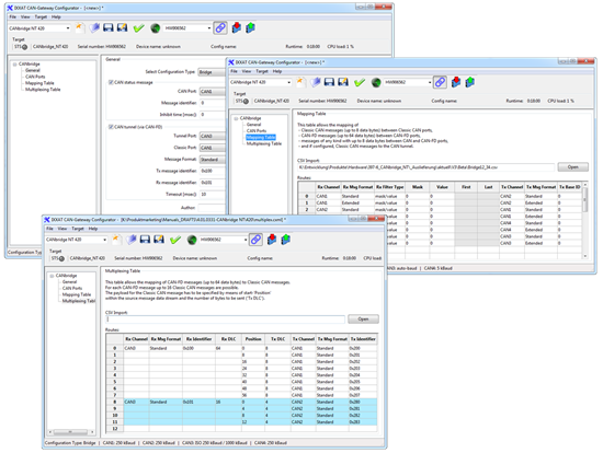
The configuration of the new CAN@net NT and the firmware upload is done with an intuitive to operate Windows configuration tool - via USB or Ethernet. With the tool, the configuration of filter, mapping, multiplexer or translation rules can be carried out very easily, without programming skills.

Windows configuration tool supporting CANbridge NT and CAN@net NT
CONTENTS OF DELIVERY
- CAN@net NT 100, CAN@net NT 200 or CAN@net NT 420
- User manual
- CD with CAN Gateway Configurator
- CAN VCI driver for Windows
- Mini USB cable
| Ethernet interface | 10/100 MBit/s, twisted pair, RJ45 connector |
| CAN transceiver | Texas Instruments SN65HVD251P |
| CAN channels | CAN@net NT 100: 1 x CAN CAN@net NT 200: 2 x CAN CAN@net NT 420: 4 x CAN (two of them with CAN FD) |
| CAN connection | CAN@net NT 100: D-Sub 9 CAN@net NT 200: Screw connector CAN@net NT 420: Screw connector |
| Max. number of bus nodes | 120 |
| CAN bus termination resistor | None |
| CAN baudrates | Standard CAN: 5 to 1000 kBit/s, CAN-FD: 5 to 8000 kBit/s |
| Power supply | 9 V to 36 V DC |
| Current consumption | typically 110 mA (at 24 V input voltage) or 230 mA (at 12 V input voltage) |
| Temperature range | Operating temperature -40 °C to +85 °C, Storage temperature -40 °C to +85 °C |
| Galvanic isolation | 1 kV for 1 sec. |
| Certification | CE, FCC, UL |
| Housing | Polyamide housing for top hat rail mounting |
| Protection class | IP20 |
| Size | approx. 114.5 x 99 x 22.5 mm |
| Weight | approx. 150 g |
• Easy coupling of CAN and CAN-FD systems and devices
• Bridging of large distances and easy remote system access using Ethernet
• Cost savings due to simple wiring
• Up to four independent CAN channels (2 CAN FD channels)
• Powerful filter, ID translation, data mapping and multiplexing functionality
• Windows configuration tool for easy configuration via USB or Ethernet
• Designed for high performance in harsh environments
| 1.01.0332.10000 | CAN@net NT 100 - 1 CAN channel* |
| 1.01.0332.20000 | CAN@net NT 200 - 2 CAN channels* |
| 1.01.0332.42000 | CAN@net NT 420 - 4 CAN channels (2 switchable to CAN FD)* |
* Please note: CAN@net NT 100, CAN@net NT 200 and CAN@net NT 420 can not be combined. For a CAN-Ethernet-CAN-Bridge please use either CAN@net NT 100, CAN@net NT 200 devices or CAN@net NT 420 devices.
Tecnologix offers support which is directly handled by development team. Do not hesitate to get in touch with our experts.
Just ask here


