Utilizziamo i cookie per rendere migliore la tua esperienza di navigazione. Per rispettare la nuova direttiva sulla privacy, è necessario chiedere il tuo consenso per impostare i cookie. Per saperne di più.
The modern, clear and very intuitive user interface, which is also rarely using popup dialogs, is crucial for a smooth experience in configuring, diagnosing, and monitoring of EtherCAT® systems.
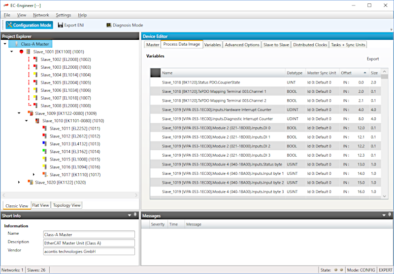
Standard and Expert View
The neatly arranged Standard View enables customers to create an EtherCAT® configuration within a view simple steps. It hides more rarely used parameters and options - these can be enabled using the Expert View.
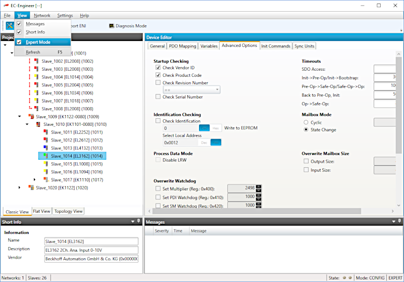
Restriction to the Essentials
The available options and dialogs of the EC-Engineer can be restricted to those topics which the control system (master system) actually supports. This is one of the significant advantages of the EC-Engineer, it helps in quickly creating configuration files with no need for multiple attemps via trial and error. The so-called EMI (EtherCAT Master Information) file will define all the properties and the scope of performance of the master system. Among others, the available cycle times, support of mailbox protocols, DC synchronization or Hot Connect can be set. The EC-Engineer is shipped with predefined EMI files which cover the functionality of an EtherCAT Class A and Class B master. Those will serve as templates to enhance or restrict the function according to the customer needs.
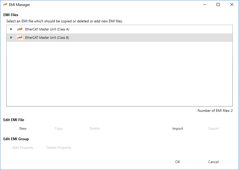
Online or Offline Configuration
When using the EC-Engineer the EtherCAT configuration can be done "offline" in the lab/office or "online" when connected with the real EtherCAT network on the machine. It doesn't matter whether the EtherCAT slaves are connected with the local Windows PC where the EC-Engineer is running, or with the control system where the control application's master stack is running. In either case the slaves and the network topology can easily be determined using the "Bus Scan" feature. In the case where the slaves are connected with the Windows PC, EC-Engineer has an integrated Windows EtherCAT Master that is able to run and verify the system. If the slaves are connected with the control system, then the master stack running on the controller will take over communication and provide all services and information which are needed for diagnosis and monitoring over to the EC-Engineer remotely (for example via TCP/IP).
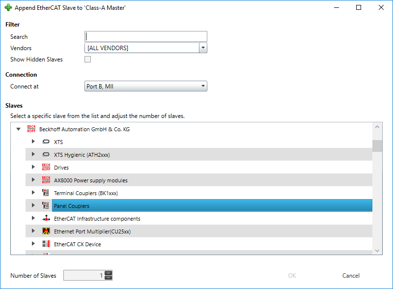
Fixed Process Data Memory Layout for the Slaves
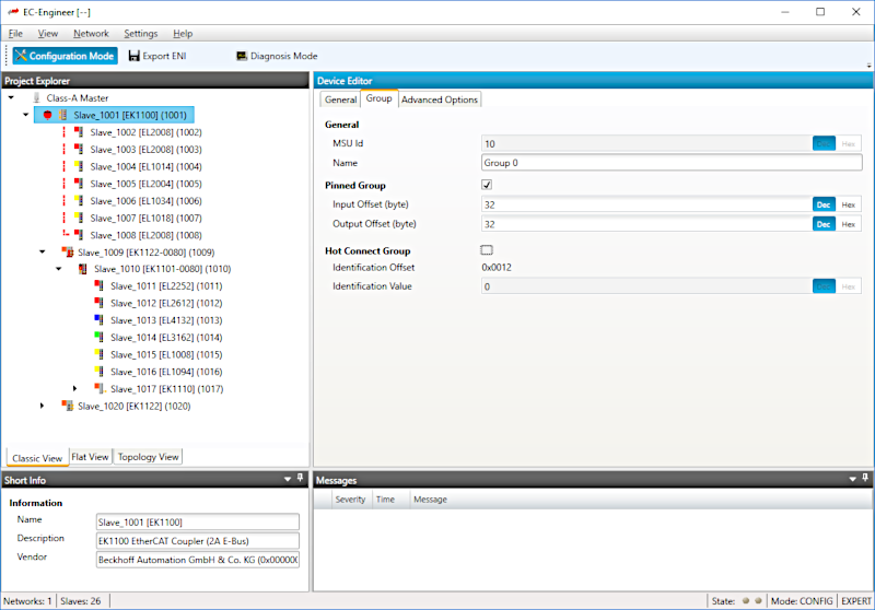
A unique feature of the EC-Engineer is the ability to set an arbitrary fixed data memory layout for a single slave or a group of slaves. It is possible to set the address of a slave to the desired fixed location in the process data area. This address then will not be changed in case any other slaves are added or removed. The desired memory location can be set to different values for input and output data.
Modular Device Profile (MDP) Slaves
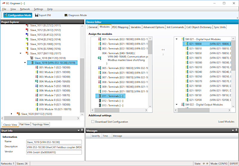
Complex slaves that are based on the Modular Device Profile (MDP) specification can be configured in a simple and clear way. The available modules (on the right side) then will be assigned to the slots (on the left side).
Powerful Diagnosis and Monitoring
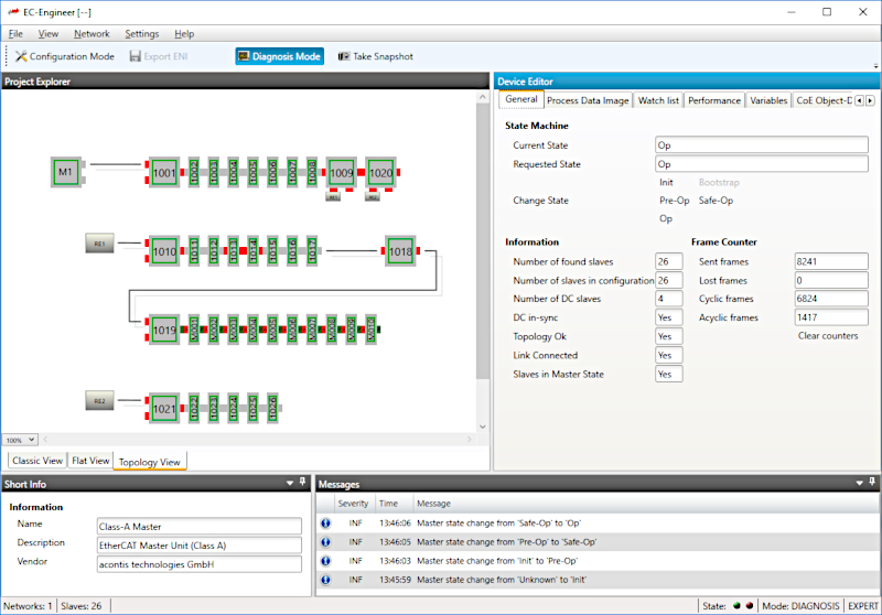
The EC-Engineer is a sophisticated tool for diagnosis and monitoring as well. Using a TCP/IP connection with the EtherCAT Master both master and slaves can be viewed and analyzed. Display of the system status and the process data content as well as more complex functions like reading the object dictionary or downloading new slave firmware are available then. A special view is provided for analyzing erroneous or incomplete EtherCAT network startup.
General Features
- Configuration of multiple master systems within one project
- EtherCAT Slaves connected to the Windows PC
- EtherCAT Slaves connected to the control system
- Tree View and Topology View
- ESI and EMI Manager
- Multiple Languages
- Modern User Interface based on Microsoft WPF technology
Configuration Features
- Import ESI (EtherCAT Slave Information) files according to ETG.2000
- Export ENI-(EtherCAT Network Information) files according to ETG.2100
- Automatic determination of the connected slaves (bus scan)
- Slave device copy and paste including all parameters
- PDO selection and configuration
- Adjustment and appending of EtherCAT slave init commands
- Transparent integration of MDP (Modular Device Profile) Slaves
- Fixed memory layout of slaves or
- Distributed Clocks (DC) Settings
- Definition of "Hot Connect" groups
- Programming Station Alias Address
- Other Master and Slaves parameters
Diagnosis and Monitoring Features
- Master and Slave State (display and control)
- Process (I/O) data (display and control)
- ESC Register (read and write)
- EEPROM (read and write)
- Master And Slave Object Dictionaries
- Mailbox transfers (Service Data Objects upload and download)
- Firmware upload and download
- Comparison of configuration and real network
System requirements
- Microsoft Windows 7 and above
- Microsoft .NET Framework 4 Client Profile
- Screen resolution at least 1024x768 pixels
- Memory as recommended for operating system
- Disk space approximately 80 MB (depend on number of ESI files)
- NDIS driver must be installed
Non esitare a metterti in contatto con i nostri esperti.
Basta chiedere qui


